This is part 1 of a series on Battery management system design.
The data presented here was collected as a part of study based Internship at Kaynes Technology, Mysore.
Most of the data here is my notes on the following resources:
- “Battery Management Systems, Volume I & II” by Gregory L. Plett along with his course.
- “Advances in Battery Technologies for Electric Vehicles” (Woodhead Publishing Series in Energy: Number 80)
- “ELECTRIC VEHICLE BATTERY SYSTEMS” by Sandeep Dhameja
- “Battery Reference Book” 3e by T.R Crompton.
Basic terminologies
- Batteries and battery packs are made up from groups of cells wired in series, parallel or a combination of them.
- Nominal Voltage is a representative voltage that depends on the combination of the active chamicals used. It dosent relate to the voltage under load, its more of an average or typical voltage.
- C rate is a relative measure of the cell electrical current eg. A 20 Ah cell should be able to deliver 20 A (“1C”) for 1 h or 2 A (“C/10”) for about 10 h (but, the relationship is not strictly linear)
- A cell stores energy in electrochemical form, which it can later release to do work, The energy release rate is the cell’s instantaneous power (mW, W, or kW)
- xEVs: Electric vehicles come in different categories and are abbreviated as xEVs
- Hybrid-electric vehicles (HEVs) These vehicles have drive provided by an electric motor and one other source ( like petrol engine ). The battery pack in these systems store small amount of energy and are used only for power boost when the vehicle must accelerate, or as a power sink when the vehicle must decelerate. They essentially have zero all-electric vehicle range and are never plugged in to recharge their battery pack; instead, the gasoline engine recharges the battery when extra power is available. An example HEV is the Toyota Prius.
- Plug-in hybrid-electric vehicles (PHEVs). These vehicles are similar to HEVs but have a somewhat larger battery pack and motor. They can operate in electric-only mode under some operating conditions, typically at lower speeds such as for residential or city driving
- Extended-Range Electric Vehicle (E-REV): Larger battery than PHEV allows some all-electric range under full-load conditions.
- Electric Vehicle (EV), a.k.a. Battery-Electric Vehicle (BEV): Battery provides only motive power.
What must a BMS do?
The primary functions of a BMS are to:
- Protect human safety of device’s operator:
- Detect unsafe operating conditions and respond
- Protect cells of battery from damage in abuse/failure cases
- Prolong life of battery (normal operating cases)
- Maintain battery in a state in which it can fulfil its functional design requirements
- Inform the application controller how to make the best use of the pack right now (e.g., by providing power limits), control charger, etc.
Basic working of an electrochemical cell
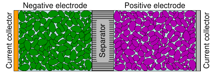
The function of the negative electrode
In an electrochemical cell, the negative electrode is often a metal or an alloy or hydrogen (lead metal or paste for PbA)
- During discharge, it gives up electrons to external circuit, is oxidized (OIL)
- During charge, accepts electrons from external circuit, is reduced
The function of the positive electrode
In an electrochemical cell, the positive electrode is often a metallic oxide, sulfide, or oxygen (lead oxide for PbA)
- During discharge, accepts electrons from circuit, is reduced
- During charge, gives up electrons to external circuit, is oxidized
Li-ion working (The process of intercalation)
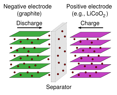
Discharge process:
- During discharge, Li exits the surface of the negative-electrode particles, gives up an electron, becoming Li in the electrolyte
- Li diffuses outward from center of negative-electrode particles to equalize concentrations, replenishing Li at particle surface (over time)
- Meanwhile, electron travels through external circuit to positive electrode
- Li joins with the electron, and Li enters positive-electrode particles at their surface
- Li diffuses into positive-electrode particles to equalize concentration (over time)
The active electrode materials are coated on both sides of metallic foils which act as the current collectors conducting the current into and out of the cell

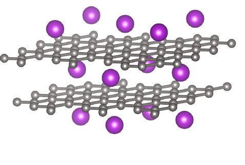
Negative electrodes for lithium-ion cells
- Presently, essentially all commercial lithium-ion cells use some form of graphite (C6 ) for the negative-electrode material
- Graphite has graphene layers of C6 structures that are tightly bonded These layers are loosely stacked and there is room for lithium to intercalate between them
Alternate negative-electrode material LTO
- Lithium titanate oxide (Li4 Ti5 O12 , LTO) is an alternative negative-electrode material
- Disadvantage: high open-circuit potential (making cell voltage low) Advantage: nearly indestructible — very long life
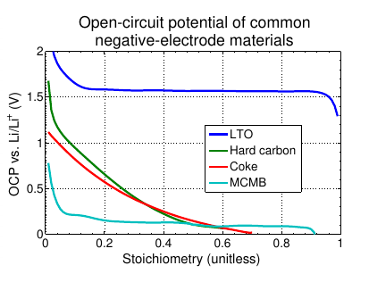
Future negative-electrode material silicon
- Using graphite, one can store up to one Li per six C atoms; using silicon, one can (in principle) store four Li per every Si atom!
- Unfortunately, while volume change for a charge/discharge cycle for graphite is around 10 %, it is around 400 % for silicon
- Therefore, silicon electrodes tend to fracture quickly and have short lives
- Possible workarounds: mix graphite with silicon, or build small forests of silicon nanowires with space in-between to allow for expansion
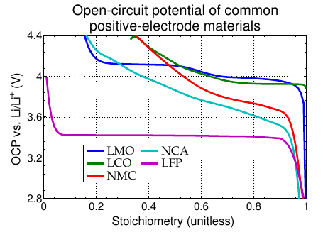
Positive electrodes for lithium-ion cells
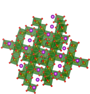
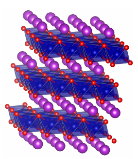
Lithium cobalt oxide (LCO)
- In 1980, John B. Goodenough discovered that Lix CoO2 (LCO) was a viable material for lithium intercalation
- Li intercalates between the layers of CoO6 octahedra
- LCO has layers, somewhat like graphite, so it is often called a “layered cathode”
Disadavntages:
- Cobalt is rare, toxic, and expensive;
- Only about half its theoretic capacity is useable (“x” can be min 0.5), else cell ages rapidly
NCM (a.k.a. NMC) is a blend of Ni, Co, and Mn, which retains the layered structure, and has properties from all three constituent metals; NCA is a blend of Ni, Co, and Al (used in tesla batteries)
Spinel cathodes
- In 1983, Goodenough and Thackery proposed LixMn2O4 (LMO) as an alternate intercalation material: Mn sits in the octahedral sites, Li in the tetrahedral
- This material has a cubic “spinel” structure. It allows 3D diffusion (vs. 2D for layered and 1D for olivine)
- LMO is cheaper and safer than LCO, but can have short lifetime due to the manganese dissolving into the electrolyte under some conditions
- Additives can be added to help prevent this, but this “art” is presently well guarded by trade secrets
Olivine cathodes
- In 1997, Goodenough proposed olivine-style phosphates as a third major category of positive-electrode material LixFePO4 (LFP) is the most common in this family
- This material is low cost, and low toxicity, but also has low energy density due to a low open-circuit potential and low specific energy due to heaviness of Fe
- 1D structure tends to have high resistance, which can be overcome in part by using very small particles and including conductive additives
In summary
- Layered cathodes (LCO, NMC, NCA) can use only around half their theoretic capacity
- Olivine cathodes (LFP) have low voltage (and very little state information in their voltage)
- Spinel cathodes (LMO) are inexpensive and non-toxic, but can degrade rapidly
What are the primary functions of a BMS?
A BMS has the following priorities:
- Protects safety of the operator of the host application; detects unsafe operating conditions and responds
- Protects cells of battery from damage in abuse/failure cases
- Prolongs life of battery (normal operating cases)
- Maintains battery in a state in which it can fulfill its functional design requirements
- Informs the host-application control computer how to make the best use of the pack right now (e.g., power limits), control charger, etc.
1. Sensing and high-voltage control
Measure voltage, current,temperature; control contactor, pre-charge; ground-fault detection,thermal management
2. Protection against
Over-charge, over-discharge, over-current, short circuit, extreme temperatures
3. Interface
Range estimation, communications, data recording, reporting
4. Performance management
State-of-charge (SOC) estimation,power-limit computation,balance/equalize cells
5. Diagnostics
Abuse detection, state-of-health (SOH) estimation, state-of-life (SOL) estimation
The issue of cost
There is a cost associated with battery management, so not all applications implement all features
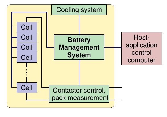
Modular design of BMS
Design extreme 1: Parallel-cell modules (PCM) Design extreme 2: Series-cell modules (SCM)
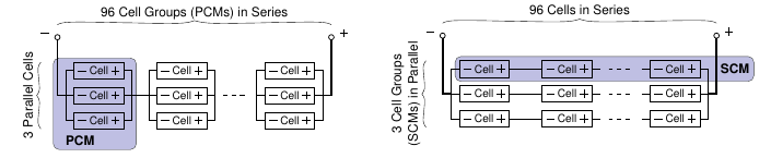
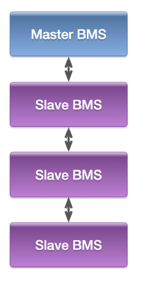
- A modular battery pack suggests a hierarchical master–slave BMS design as well
- One “slave” BMS unit is associated with each module
- Module’s cells welded/bolted to slave PCB, minimizing wiring and wiring losses
- Slave has electronics for voltage measurement, cell balancing
- There is then normally a single “master” unit for each pack
- Master measures pack current, controls contactors
- Communicates with slaves via daisy-chain or star architecture
- Master/slave communication uses few (e.g. two) wires—minimizes wiring-harness nightmare
BMS slave role
BMS slave needs to:
- Measure voltage of every cell within the module
- Measure temperatures Ideally of every cell, but in many packs some temperatures are estimated, especially if the pack has cells in parallel
- Balance the energy stored in every cell within the module this is needed as cells have different efficiencies, self-discharge rates, etc.
- Communicate this information to the master
- Is slave design reusable?
- Often “yes”, assuming electronics flexible in terms of number of cells monitored, physical size matches different applications While electronics design may be reusable in most cases, may need to redesign PCB footprint to fit individual applications For high volumes there may be overall cost savings in developing a specific slave optimized for a given module
BMS master role
BMS master needs to
- Control contactors that connect battery to load
- Monitor pack current, isolation
- Communicate with BMS slaves Communicate with host- application controller
- Control thermal-management
- Is master design reusable?
- More difficult than for slave designs Master needs to be more flexible; for example, Number and type of contactors it controls Types of current sensors used Ways it connects to charger, thermal management system
1a. Battery-pack sensing: Voltage
All cell voltages are measured in a lithium-ion pack
- Indicator of relative balance of cells
- Input to most SOC and SOH estimation algorithms
- Safety: overcharging a lithium-ion cell can lead to “thermal runaway,” so we cannot skip measuring any voltages
Some methods for analog-to-digital conversion
At the most basic level, voltage is measured using an analog-o-digital converter
There are several common ADC architectures; for example,
- A direct-conversion or flash ADC uses a bank of comparators and fixed reference voltages, outputs code of closest reference (fast, expensive)
- Successive approximation compares input to output from DAC and uses feedback to modify DAC signal, resolving input to desired accuracy (slow, inexpensive)
- Delta-sigma uses oversampled 1-bit flash ADC to encode difference ( ) between approximation and input, sums ( ) differences and filters to give final high-resolution result at desired slower sample rate (very popular)
- The resolution of an ADC is the smallest change in the input signal that can be measured; it is also the step size between consecutive ADC output codes (typically 16bit adc has a resolution of 76uV)
- Resolution for a M bit ADC is the full scale voltage difference divided by 2 to the power of M
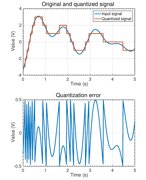
Accuracy of an ADC
The accuracy of an ADC has to do with the absolute difference between the reported value and the true value:difference may be due to several sources
- Quantization error (unmeasurable value between)
- Offset error (constant difference between ideal and measured value over whole measurement range)
- Gain error (difference between slope of ideal and measured value over whole measurement range, expressed as %)
- Nonlinear error (deviation between actual and ideal step widths, expressed as ADC counts)
Chipsets
Special chipsets are made to aid high-voltage BMS design
- Low-cost “dumb” measurement chips used in modules, proximate to cells; high-cost computational processing in distant master unit
- Special chips implement difficult task of highly accurate A2D voltage sensing with high common-mode rejection and fast response in high-EMI, high-heat, high-vibration environments
- Can often be placed in parallel for redundant fault-tolerant designs. Multiple vendors make chipsets (e.g., Analog Devices, Maxim, Texas Instruments)
Example chipset: LTC6811
example (LTC6811) designed by Analog Devices (formerly Linear Technology)
- Monitors up to 12 cells in series in a module, 100s of cells in series in pack
- Has built-in isolated communications between daisy-chained parts
- Supports internal or external cell- equalization circuitry
- Powered by module itself, or externally
- Measures up to five temperatures (more with some external circuitry)
Selecting a chipset
Points to be considered in a design:
- How many cells can each IC monitor?
- How many cells total can be monitored?
- Does it support passive/active balancing?
- What is the measurement accuracy?
- How many temperature measurements can be made?
- How many wires to communicate from IC to IC?
- What is chipset availability and cost, per cell?
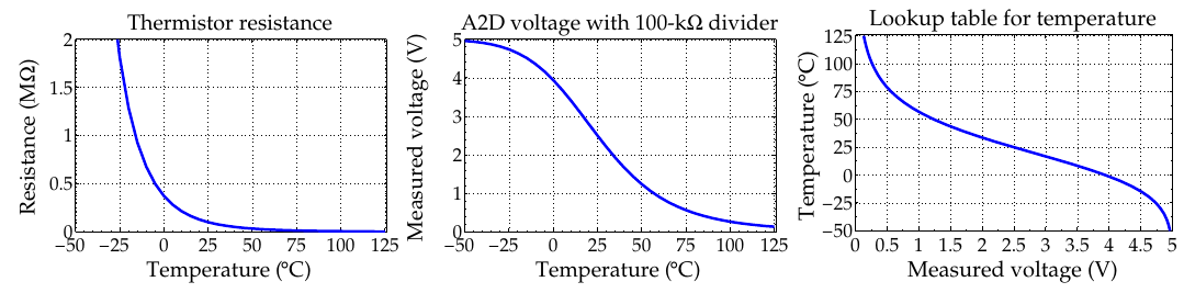
1b. Battery-pack sensing: Temperature
Battery cell operational characteristics and cell degradation rates are very strong functions of temperature
- Don’t charge at low temperature; control thermal management systems to keep temperature in “safe” region
- Unexpected temperature changes can indicate cell failure or impending safety concern
- Ideally, we measure each cell’s internal temperature; but, With accurate pack thermal model, can place sensors external to one or more cells per module and calibrate internal temperature
Measurement devices:
- Thermocouple (uses amplifier and ADC)
- Thermistor (uses voltage divider circuit)
Voltage-divider + thermistor example
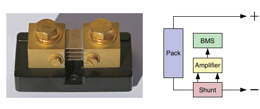
1c. Battery-pack sensing: Current
Battery pack electrical current must be measured to monitor safety, log abuse, and inform SOC and SOH algorithms
Using :
-
Shunt current sensor (Kelvin four-wire)
-
Hall-effect current sensing
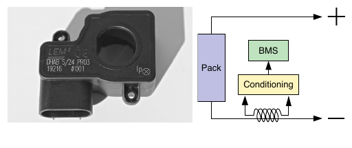
Both methods have advantages and disadvantages and both are in common use in BMS today
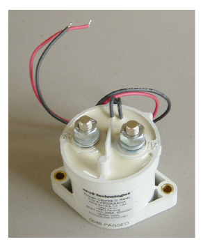
1d: High-voltage contactor control
When not in use, the battery pack internal high-voltage bus is completely disconnected from the load at both terminals
- Dis/connecting pack at both terminals requires two high-current capable relays or “contactors”
- A low-voltage/low-current signal activates the contactor, closing an internal switch that connects its main terminals
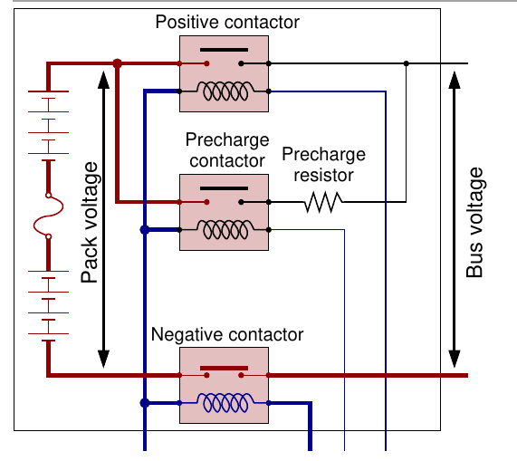
- As load is often capacitive, if both contactors were closed simultaneously, enormous current would flow instantly, potentially welding the contactors closed or blowing a fuse
- So, a third “pre-charge” contactor is used
Contactor procedure:
1e. Isolation sensing
Isolation sensing detects presence of a ground fault
- Primary concern is safety: Is it safe to touch a battery terminal and chassis ground at the same time?
- Battery “should” be completely isolated from chassis ground, so “should” be no problem
- FMVSS says isolation is sufficient if less than 2 mA of current will flow when connecting chassis ground to either the positive or negative terminal of the battery pack via a direct short
Procedure:
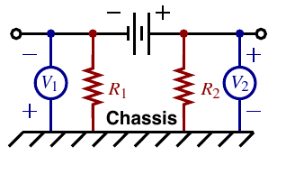
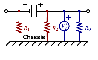
For fault on low side

Isolation is deemed sufficient if Ri>Vb /0.002 or R1 > 500Vb
1f. Thermal control
Important to keep battery-pack cells at a “comfortable”temperature to ensure safety and to extend life
- Also important to keep cells at a uniform temperature for consistent aging (also reduces need for many temperature sensors)
- Present commercial systems use either air or liquid systems, and some reports indicate that range and life are negatively impacted by air systems
- Active heating and cooling while vehicle plugged in can extend life, shorten charge times
How can a BMS protect the user and battery pack?
BMS requirement 2: Protection
BMS must provide monitoring and control to protect:
- Cells from out-of-tolerance ambient operating conditions
- User from consequences of battery failures
High-energy storage batteries can be very dangerous:
- If energy is released in an uncontrolled way (short circuit, physical damage), can have catastrophic consequences
- In a short circuit, hundreds of amperes can develop in microseconds; protection circuitry must act quickly state
What to protect against
Different applications and different cell chemistries require different degrees of protection
- Failure in a lithium-ion cell can be very serious: explosion/fire
- Protection is indispensable in automotive environment
- Protection must address following undesirable events or conditions:
- Excessive current during charging or discharging
- Short circuit
- Over voltage and under voltage
- High ambient temperature, overheating
- Loss of isolation
- Abuse
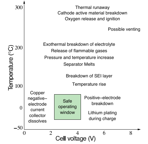
Overcurrent/overtemperature protection
When possible, fallback protection paths should be implemented
- Red = cell-manufacturer specified region where cells will most likely be subject to permanent damage
- Anywhere else “okay” but need a margin of error
- Generally design to limit cell’s operating conditions to smaller “safe” region, shown here in green
- Safety devices are then specified to constrain cells to safe region
- White = safety margin
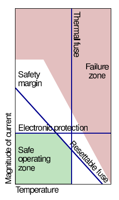
Overvoltage/overtemperature protection
Similar for voltage limits:
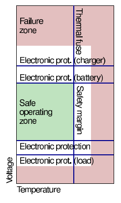
But, each protection device added into main current path increases battery impedance, reducing power delivered to load Examples of protection devices include:
- Thermal fuse: Opens contactor when the temperature exceeds limit.
- Conventional fuse: May not act quickly enough
- Active fault detection: BMS monitoring for fault conditions
Fault detection/tolerance
- Another aspect of protection is detecting, withstanding, and (when possible) rectifying faults
- State-of-art BMS use processors having dual CPUs that execute the same instructions at slightly different times on different cores, then compare results
- Slaves often can detect most cell faults without intervention of the main processor
- Cell over/under voltage, over/under temperature, redundant sensing, etc.
- Serious slave faults should be able to shut pack down without using master microprocessor
- Some more complex faults (for example isolation) must be detected by the software(Algorithm)
- The link between master and slaves must have high EMI immunity
Standards
Different applications have different standards for safety
- Passenger cars having maximum gross vehicle mass up to 3500 kg fall under ISO26262:2011
- Electric motorcycles fall under ISO/PAS 19695:2015 (similar to ISO26262)
- Larger trucks over 3500 kg, such as Ford F250, 350, Chevy Silverado 2500, as well as semis, buses, etc…) fall under IEC61508
- While these safety standards have the same goals they are different in application
- Use different “safety integrity levels” (SILs), evaluated in different ways
- Very difficult to design to all these standards simultaneously Standards are complex—require study of their own to understand how to comply most likely 40% of the code written for BMS is to ensure these standards.
3 How must a BMS interface with other system components?
3a. Communication via CAN bus
- Control Area Network (CAN) bus is industry ISO standard foron-board vehicle communications
- Designed to provide robust communications in the very harsh automotive operating environments with high levels of electrical noise
- Two-wire serial bus designed to network intelligent sensors and actuators; can
operate at two rates:
- High speed (e.g., 1M Baud): Used for critical operations such as engine management, vehicle stability, motion control
- Low speed (e.g., 100 kBaud): Simple switching and control of lighting, windows, mirror adjustments, and instrument displays (etc.)
Format of CAN-bus packet
The protocol defines the following:
- Method of addressing the devices connected to the bus
- Data format (the “message”)
- Transmission speed, priority settings, and sequence
- Error detection and handling
- Control signals
A typical packet(frame) in CAN bus looks like :
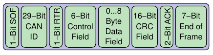
Abbreviations : SOF - Start of frame; RTR- Ready to receive; CRC - cyclic redundancy check; ACK-acknowledgement bit
Data frames are transmitted sequentially over the bus.
3b. Charger control
Battery packs are charged in two ways:
- Random: Charge delivered in unpredictable patterns; e.g., regenerative braking and are Control by providing inverter power limits
- Plug-in: For EV/PHEV/E-REV
- Control charger current, voltage, balancing
- Often CP/CV; more exotic methods possible (in the research phase)
- Heating systems may be required to increase charge efficiency and to increase battery longevity
What limits fast charging?
Passenger vehicles require approximately 200–300 Wh / mile
- For 300 mile range, 60–90 kWh capacity, charge in 3 min (typical petrol refill time) . requires a rate of up to 1.8 MW!
- Domestic 15 A 110 V (US) or 1 5 kW “level 1” service charges pack in 40–60 h
- Domestic 30 A 220 V (US- high power sockets) or 6 6 kW “level 2” service charges pack in 10–15 h
- DC “level 3” (CHAdeMO) fast charging, 500 V, 125 A can provide up to 80 % charge in 30 min
- Tesla “level 3” fast charging for model S can provide 50 % charge in 20 min So, limit is usually the electrical service, not the battery pack
3c. Log book function
- For warranty and diagnostic purposes, BMS must store a log
of atypical/abuse events
- Abuse type: out of tolerance, voltage, current, temperature
- Duration and magnitude of abuse
Can also store diagnostic information regarding
- Number of charge/discharge cycles completed
- SOH estimates at the beginning of each driving cycle And much more…
- Data stored in nonvolatile (e.g., FLASH) memory and downloaded when required
3d. Range estimation
How far can I drive before available energy is depleted? Heavily influenced by environmental factors:
- What are the vehicle characteristics?
- How is the vehicle being driven (gently/aggressively)?
- Are there a lot of hills, a lot of wind?
- Is it warm or cold out?
- At present, it appears that each OEM will have their own range algorithms
BMS requirement 4: Performance management
Battery applications need to know two battery quantities:
- How much energy is available in the battery pack
- How much power is available in the immediate future
Knowing energy is most important for applications such as EV: Tells me how far I can drive Knowing power is most important for applications such as HEV: Tells me whether I can accelerate or accept braking charge
Both are important for applications such as E-REV/PHEV
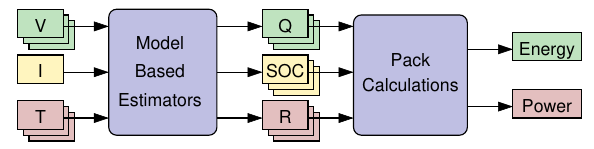
Why must we estimate energy, power?
We Can’t measure available energy or available power directly. Instead, must estimate these values.
- To estimate energy, we must know (atleast) all cell states-of-charge Zk and capacities Qk
- To estimate power, we must know (atleast) all cell states-of-charge Zk and internal resistances Rk
But, cannot directly measure these parameters either! Therefore, must estimate SOC, SOH
Available inputs include all cell voltages, pack current, and temperatures of cells or modules.
There are both good and poor methods to produce estimates: Poor methods are generally simpler to understand, code, and validate, but yield less-accurate results
Impacts of a poor estimator can be:
- Abrupt corrections when voltage or current limits exceeded,
- leading to customer perception of poor drivability, or
- Overcharge or overdischarge, which damages cells, or
- Compensating for uncertainty by overdesigning pack All of these have costs in dollars, weight and/or volume
A good way to do SOC estimate is to implement Kalman filter
Whats left to explore ?
- Article 2: How to model cells, needed by algorithms
- Article 3: Advanced methods for SOC estimation
- Article 4: SOH estimation
- Article 5: Balancing and power-limits estimation