This post is about the construction of a novel stove stand that harnesses energy wasted during cooking. It was originally a experimental project from my school days (developed from 9th - 12th grade). I have tried to document it as best as I can. It has won over many science exhibitions. I hope you find it interesting.
Introduction
Today there is energy crisis every where. Even small amount of energy that we can conserve is of great importance. But we are wasting a large amount of heat energy in stove, furnaces in various industries etc. Growing technology have tried to conserve as much of energy as possible. But there is still a large opportunity to conserve energy. In this project work we have applied the principle of thermoelectric effect to utilize waste heat from gas stove and store it for later use.
The problem
The primary prblem we are trying to solve today is that of the LPG gas stove.
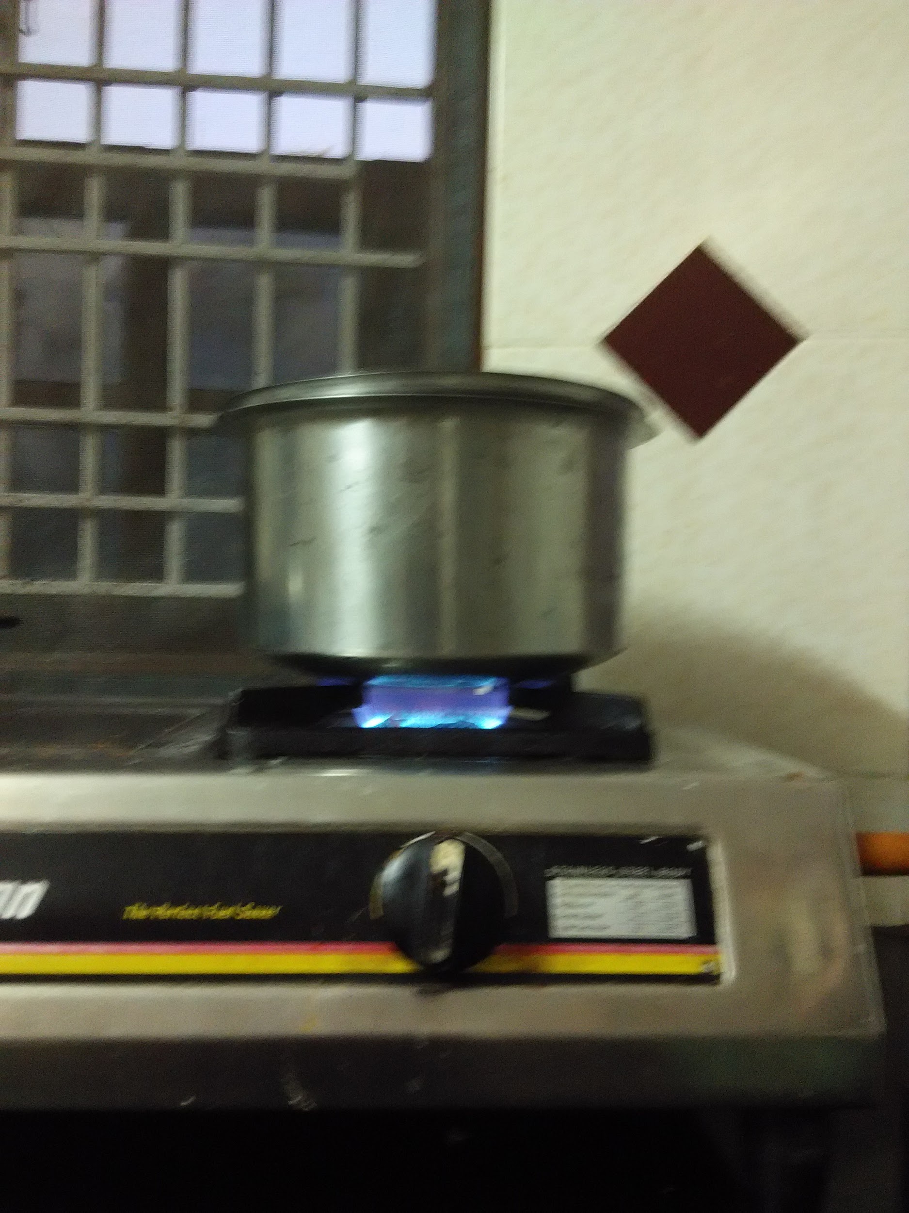
Example of an LPG stove at Indian households
The LPG gas stove is a very common device used in every household. It is used for cooking food. The LPG gas stove is a very inefficient device. It wastes a lot of heat energy. The heat energy is wasted in two ways. One is the heat energy that is wasted by the flame. The other is the heat energy that is wasted by the utensil. The heat energy that is wasted by the flame is very high. The flame not only heats the utensil but also the surrounding air. This can easily be felt as cooking in the kitchen for a long time makes the kitchen very hot. This heat energy is wasted. This is also very evident in the case of street food vendors also common in India.
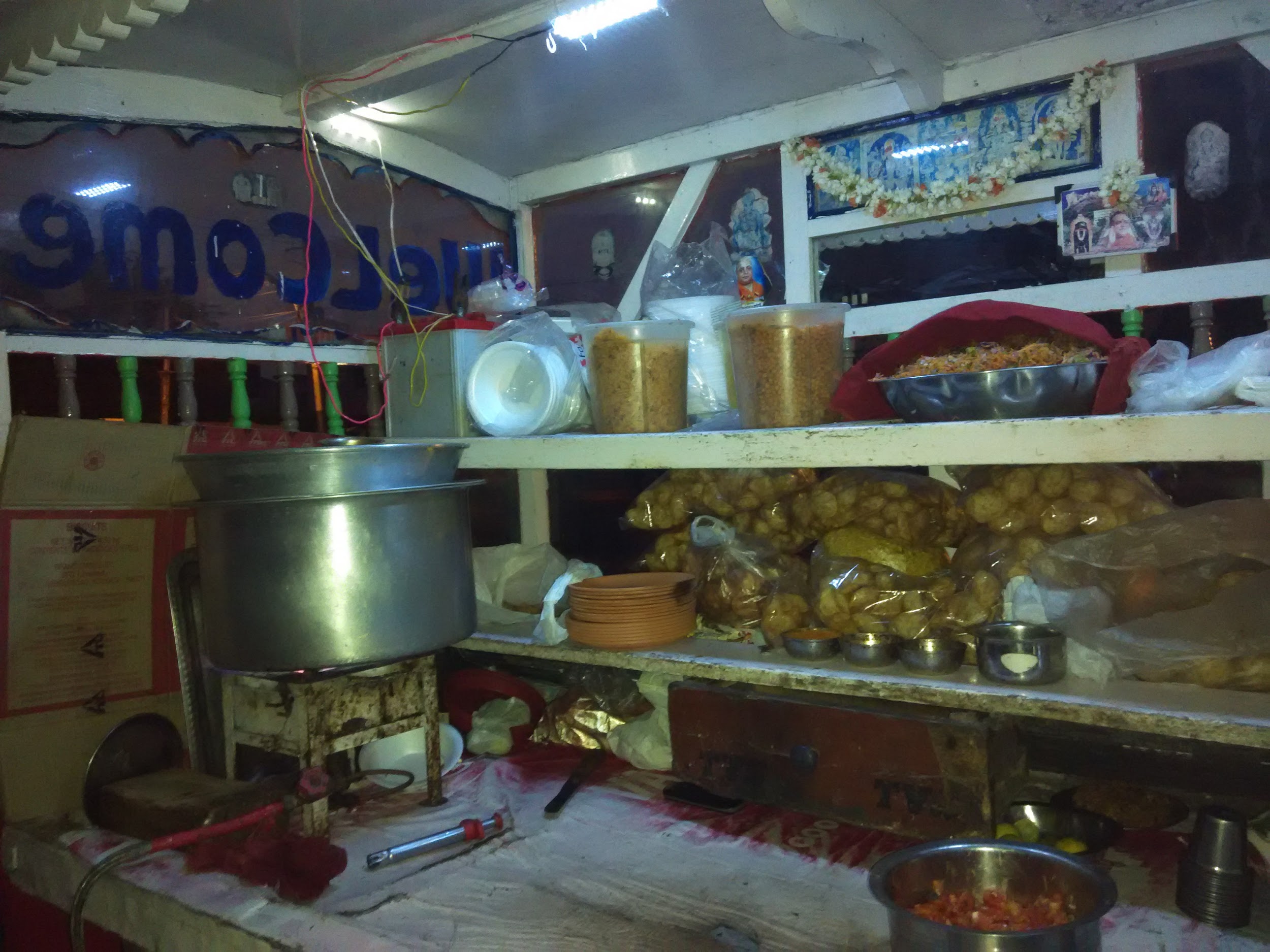
Example of a street food vendor
The solution
Model 1 : The first prototype
1. Scientific principle involved
Seebeck effect : This project work is based on the principle of Seebeck effect. The Seebeck effect is the conversion of temperature differences directly into electricity and is named after Thomas Johann Seebeck. Metals respond to the temperature difference in different ways, creating a current loop and a magnetic field. The Seebeck effect is a classic example of an electromotive force (emf) and leads to measurable currents or voltages in the same way as any other emf.
Electromotive force \(Emf = Sc * T\) (in joule).
Where Sc - Seebeck coefficient a property of the local material, T - Gradient in temperature .
The Seebeck coefficients generally vary as function of temperature, and depend strongly on the composition of the conductor. Thermoelectric generators are used for creating power from heat differentials.
Working Principle of thermoelectric generator (TEG)
Thermoelectric generators are solid-state heat engines that operate according to the Seebeck Effect. A thermoelectric generator is made of many pairs of p-type and n-type elements. The p-type and n-type have positive and negative Sc respectively. Connecting a p-type element to an n-type element creates a voltage potential across the junction. This voltage potential is proportional to the differences in the Sc in each element and the temperature of the junction. Soon, each hole and electron that “switch sides” will be in equilibrium and act like a barrier, preventing more electrons or holes from migrating. This is called the depletion zone. Heating this depletion zone area and cooling other ends of the element can break down this depletion zone. The mobile holes in the p-type are excited by the heat and move further into the element with the extra kinetic energy. The same happens to the mobile electrons in the n-type material. The net effect: many of the holes pile up at the cold end of the p-type element and many of the electrons pile up at the cold end of the n-type element, thereby creating a voltage potential across the p-n junction. By placing an electrical load or wire from the cold end of the p-type element to the n-type element, the electrons from the n-type element will flow at towards the end of the p-type element . In response, a hole from the p-type element will migrate towards n-type. The end effect is current flow across a voltage potential (from the p-n junction), and electrical power is created. This power is a function of many things such as temperature difference, Sc, and the electrical load that connects the sides.
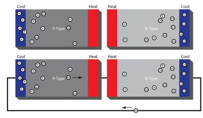
Explanation of the thermoelectric generator
Experimental method
Basic model of a Novel Stove Stand
This is a practical application of thermoelectric effect. Circuit of copper - copper oxide junction on the hot wire and an opposing copper oxide - copper junction on the cold wireis connected. Copper oxide, also acts like a thermistor with a very high negative temperature coefficient. Even the “cold” wire still gets hot enough that the resistance of the copper oxide drops relatively to a very low value - enabling current to flow.
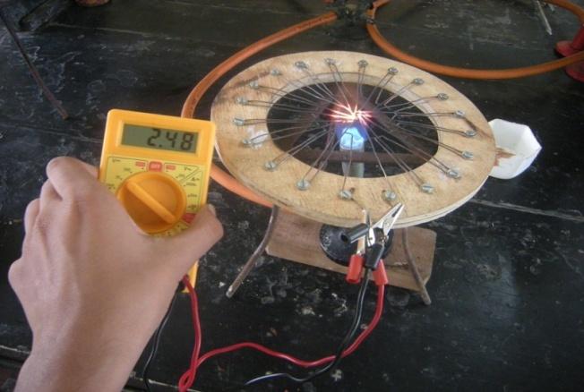
The first prototype of the Cu-CuO based stove stand
The current also depends on the following factors
- the thickness of copper wire used
- the hot copper oxide conductor not touching its neighbour
- the no. of junction in series
- the distance between the hot and cold junctions
Improvised model of Novel stove stand
This is practical application of thermoelectric effect. Four sets of TEG connected in a series to an aluminum metal box around the stove and the heat energy is converted into electrical energy. This is presented as “Model 2 : The second prototype” below.
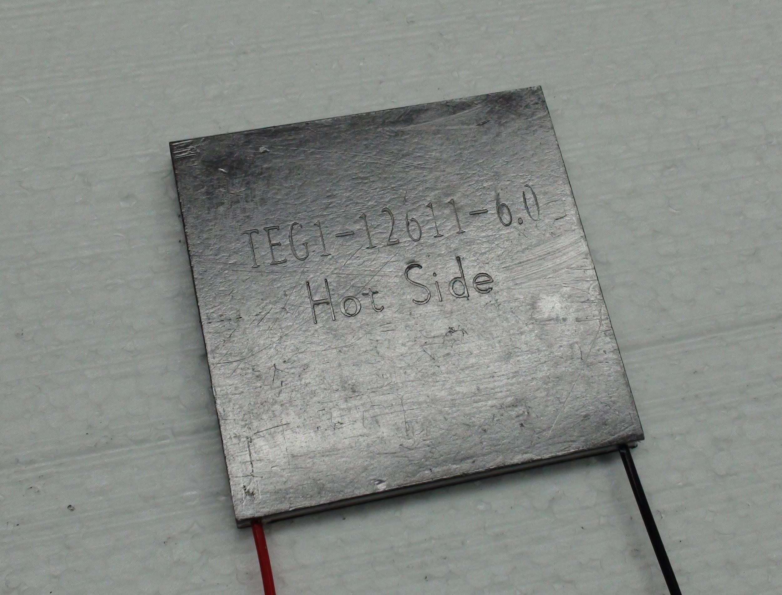
Example of a TEG device
Observation and Results
The energy generated by the Cu-CuO based stove stand is not sufficient to charge a mobile phone. But it can be used to light up a LED. but it is not efficient to capture all the wated energy, a more efficient device design is required to capture the extra flames and a better heat to electricity device must be employed (TEG or TEC). This is presented as “Model 2 : The second prototype” below.
Conclusion:
Using this novel stove stand, the heat energy that was being wasted can be converted into electrical energy which can be further utilized for charging the devices viz., mobile charger and other electrical applications.
Model 2 : The second prototype
Aim / Objective
Converting waste heat energy liberated into useful electrical energy using a device called thermoelectric generator and powering various electrical gadgets. These energy wasted may be from sources like heat wasted during cooking food in gas stove in house, hotels and in other everyday situations like furnaces etc. This prototype was desinged keeping in mind the flaws from the first design where the flames were not captured efficiently and the device was not efficient enough to convert the heat energy into electrical energy.
Materials & Methods / Experimentation
Matierls and Methods
In this model four sets of TECs used as makeshift thermoelectric generator are connected in series to a zinc metal box around the stove and the heat energy is converted into electrical energy. The output is about 5.5 V against a 10 ohm load resistor, the electricity is stored into a power bank and its output is taken to charge a mobile phone or other light gadgets.
The device can be made in two versions viz. economic and efficient.
The efficient version includes four TEG’s (Thermoelectric generator) which are rated for its, high temperature to electricity conversion efficiency and can operate over greater temperature ranges.
The economic version include a cheaper but less efficient device called thermoelectric cooler (TEC) which can be made to work in the same way as a thermoelectric generator (a reverse application of TEC). We are taking the latter version in the model.
Experimentation
This project work is based on the principle of Seebeck effect. The Seebeck effect is the conversion of temperature differences directly into electricity and is named after Thomas Johann Seebeck. The Seebeck effect is a classic example of an electromotive force and leads to measurable currents or voltages in the same way as any other emf.
A thermoelectric generator is used in this device. Thermoelectric generators are solid-state heat engines that operate according to the Seebeck Effect.
Schematically the model can be represented as in fig 2
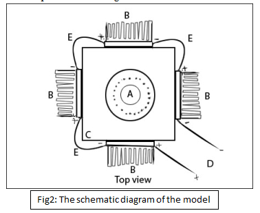
Fig2: The schematic diagram of the model
-
Here “A” represents the burner. The device is built with the burner as the center.
-
“B” here is the heart of the device. It is the thermoelectric generator, it is sandwiched between the wall “C” and the aluminum heat sink (the one which has saw like teeth).The device receives its heat from “C” and the heat sink cools it from the other side. Each Thermoelectric device has two leads coming out of it. One positive and the other negative. All the TEG are connected in series.
-
“C” represents the walls of the device which is made of zinc sheet.
-
“E ” represents the wire inter connecting all the four TEGs in series
-
“D” is the final wire connecting the first and the fourth TEG, One here is positive and the other is the negative wire. The output is taken from these leads.
The device is to be kept beside the flame of the stove (or if possible integrate the device into the stove itself.) and the utensil is kept inside the walls of the device. When cooking starts, the flames from “A” heat up the plates “C” and that of the utensil. This heat is absorbed by the plates “C” and is transmitted to the TEG (“B”) by conduction. TEG converts this heat in to electricity and is outputted through the leads (E). Since they are all connected in series the voltage add up to the final voltage in “D”. The aluminum heat sink helps cool the other side of the TEG to increase the temperature gradient .The output through “D” can be feed into the gadgets required like LED lamp or a mobile phone charger etc. through a stabilizing circuit (as per requirement).
Calculations
A plot of Volts (under a constant load resistor) vs. Time is made by using the average of two observations done on two different days.
To find the power captured by the walls of the device (which would have been dissipated into the atmosphere if the device wasn’t kept.) a plot Temperature vs. Time graph is made, data for which is taken from the above two experiment and is then averaged. At the equilibrium point the energy absorbed by metal sheet is equal to the energy radiated out thus a temperature equilibrium is achieved. A slope of the graph at this point gives us instantaneous rate change of temperature with respect to time i.e. . Then using the formula given below (eq1) which is the absorbed heat is calculated. The equation eq 1 is obtained by differentiating Q = m S ΔT Where Q is heat; m is the mass; S is the specific heat; and ΔT is the change in temperature
\(\frac{dQ}{dt}=mS\frac{dT}{dt}\)
Results / Observation / Findings
The observations have been divided into two types of calculation. - 1) Voltage based and - 2) temperature based.
1) Voltage based calculations
The energy produced by each of the device is calculated based on observed data (for TEC) and collected data (for TEG). The table and graph below shows the results and calculation. Here energy saved is calculated using \(E = V^2 t/ R.\)
Graph 1 shows a curve that initially increases sharply and then stabilises at around 5.5 V. First the energy saved by a home which uses this device for two hours a day is calculated then for a month and a year. Next Energy saved by a City with 10,000 families using this device in a year is taken into consideration.
The economical version (TEC type) of the device can generate 3.025 W but its fabrication cost comes out to be Rs 750. However the efficient version (TEG type) could generate 20 W of power with the cost of production coming at around Rs 4000 ($48).
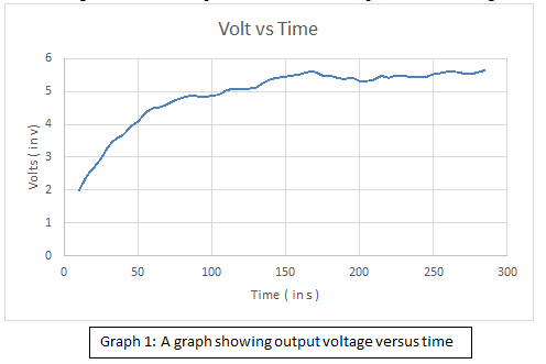
Graph 1: A graph showing output voltage versus time
| Table 1. Showing the comparison on the energy saved by the two devices | ||
|---|---|---|
| Energy saved the by economic version (TEC) | Energy saved by more efficient version (TEG) (expected results **ref 1 ) | |
| Electricity produced by the model | 5.5V (under 10 ohm load resistor) | 21.2V , 1 A |
| Energy saved by a home which uses this device for two hours a day | 2.17x\(10^4\) J | 1.526x10⁵ J |
| Energy saved by them in a month | 6.53x\(10^5\) J | 4.579 x \(10^6\) J |
| Energy saved by them in a year | 8.74 x \(10^6\) J | 5.571x \(10^7\) J |
| Energy saved by a city with 10,000 families using this device (in 1 year) | 8.74 x \(10^{10}\) J | 5.571x \(10^{11}\) J |
2) Temperature based calculations
These calculations are made to find out the feasibility of the device. I.e. to know the input output ratio and to know the effect of the device on heating.
To find conversion ratio
Consider the following Temperature vs Time plot.
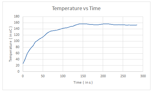
Graph 2: A graph showing temperature versus time
At equilibrium point (just before temperature becomes constant) the slope was found to be 0.3. Thus using Eq 1 and taking \(m = 0.052 kg\) (calculated value); \(S = 0.093 kcal/kg {}^{\circ}C\) (** ref 2) and \(\frac{dT}{dt}\) as 0.3 (from graph). We get \(\frac{dQ}{dt} = 0.052 *93*0.3 = 1.4508 cal/s = 6.07 watts\). Further average power expended by the aluminium heat sink as P = mSΔT/Δt and taking m = 0.952 kg; ΔT= 29.5; Δt = 130 s (calculated values) and \(S = 0.22 kcal/kg {}^{\circ}C\) (** ref 2).
So \(P = (0.952*220*29.5)/130 = 47.52 cal/s = 198.98\) watt. \(P_{(total)} = 198.98+6.07 = 205.05\) watt.
So out of 205.05 watt absorbed only 3.025 watt is converted to electrical energy implying 1.475% efficiency which is quite low but still significant and is in accordance with the specs of a TEC.
2) To find the effect on cooking
To study the effect of the device on the cooking process, we measured the time taken to boil 100mL of water in two scenarios one without the device and one with the device.
Table 2: Table showing boiling time of water with and without the device
| Sl.no | Water boiled | Time taken |
|---|---|---|
| 1 | Without the device | 1 min 35 s |
| 2 | With the device | 1 min |
The data confirms that the device doesn’t hinder the cooking process rather helps cook faster. The decreased time in cooking is due to the fact that those heat waves which would have escaped to the atmosphere are now confined by the walls of the device thus more waves heat up the utensil thus decreasing the cooking time.
Significance / Conclusion
Using this novel stove stand, the heat energy that was being wasted can be converted into electrical energy which can be further utilized for charging the devices viz., mobile charger and other electrical applications.
People who involve in cooking activities for a long time have a great use for this device. These include but not limited to
-
Cooks at hotels
-
Street vendors like chat vendors or tea seller
-
People with a 24x7 fireplace and anywhere else where too much of waste heat is generated. However the design of the model has to be adjusted suit the size of the above application.
Innovation / Novelty
It’s an innovative device to save energy from heat wasted while cooking. The device could be made built inside the stove itself for the generation of electricity which can be stored inside a battery for later use. Ideally the output could be directly connected with a LED lamp to light up the kitchen and when not required, the energy would be stored in a battery.
Data source
**ref 1 http://www.customthermoelectric.com/powergen.html
**ref 2 http://www.engineeringtoolbox.com/specific-heat-metals-d_152.html